1. The Model Concept and Its Limits, Validity Conditions of the Formulas
The following will demonstrate how concrete predictions about the formation and characteristics of snow cover halos can be derived from the previously described model concept. These predictions can be quickly generated using the computer program I developed for this purpose. However, it must not be overlooked that the spindle body is merely a model, which, like any model, neglects certain aspects of the phenomenon. This neglect arises because a fixed value for the deflection angle (the minimal deflection) is used, and thus always a body of the same shape (similar bodies) is used. This means that the following formulas (and also the earlier versions of the computer program) refer to the inner edge of the halo. The larger deflection angles that occur even for the same color as well as the colors themselves are ignored. Furthermore, a point light source is assumed. This condition is approximately met in practice, but caution is advised with spotlights with reflectors. Only one coordinate system is established, which is why the representation corresponds to monocular vision. One last condition is the flat snow cover and the measurement of the observer and lamp height perpendicular to this plane. When describing frost crystal halos at earthly light sources, a neatly trimmed lawn is assumed to ensure the uniqueness of the intersection curve (the halo ring). Additionally, the curvature of the earth must not yet become disturbingly noticeable.
2. Explanation of Coordinates, Projections

To mathematically represent bodies and positions in space, a coordinate system like the one shown is used (origin at the observer's feet, right-hand system, x-axis pointing towards the sun or lamp). Since the observer's eye level, the lamp height, and the distance of both foot points are the only parameters entered in the formulas as length measures, the division of the axes depends on the chosen unit of length (meters are recommended). From the observer's point of view, the positive y-axis is on the left side, the negative on the right. This allows for a cross-section in the x,y-plane without complex rotations. To view in the direction of the negative x-axis, the observer must turn. The z-axis strictly applies only to one eye. However, polar coordinates, meaning angle values and a distance indication, are more practical for use. In this case, the distance indication can be omitted, because it mainly concerns the direction of light incidence given by two angles. To define these angles, imagine the viewer standing in a sphere - the so-called celestial sphere. Its radius is arbitrary because the distance indication is unnecessary. It can be imagined touching the x,y-plane or smaller, so as not to encounter problems with the axes. A grid (like the geographical one) is laid on the sphere. Now the direction to a point in space can be determined by azimuth (corresponds to geographical longitude) and elevation (corresponds to geographical latitude). The zero point of these angle coordinates lies on the horizon (that is the plane parallel to the x,y-plane on which the observer's eye lies, or the horizontal great circle of the grid) in the direction of the sun or light source. If a point is above the horizontal plane, its elevation is positive, otherwise negative. If the y-value of a point is negative, so is its azimuth, and vice versa (if the y-value is 0 and x is any positive, the azimuth is 0, for negative x 180°, with the sign being arbitrary). It is important that the azimuth, in contrast to the angle used in astronomy, refers to the direction towards the sun and not to the north or south direction. Now it must be clarified how the coordinates can be converted into one another. The tangent of the elevation is obtained by dividing the vertical difference (z-value minus eye level) by the distance of the point on the snow cover (determined according to the Pythagorean theorem from x and y). The tangent of the azimuth is the ratio of y to x.
\begin{equation}
\tan \varphi = {z - h_B \over {\sqrt{x^2 + y^2}}}
\end{equation} \begin{equation*}
-90° \leq \varphi \leq 90°
\end{equation*}
\tan \varphi = {z - h_B \over {\sqrt{x^2 + y^2}}}
\end{equation} \begin{equation*}
-90° \leq \varphi \leq 90°
\end{equation*}
\begin{equation}
\tan \lambda = {y \over x}
\end{equation} \begin{equation*}
-180° \leq \lambda \leq 180°
\end{equation*}
\tan \lambda = {y \over x}
\end{equation} \begin{equation*}
-180° \leq \lambda \leq 180°
\end{equation*}
Since the azimuth is always counted on a horizontal plane, the z-value has no effect on it. It follows that a vertical rod represents a constant azimuth. The light rays emanating from it intersect the sphere in a great circle (the radii of the great circles correspond to the sphere's radius, those of the small circles are smaller). Thus, every line of constant azimuth (called a circle of altitude, since height is measured along these circles) is a half great circle through the zenith (direction of the positive z-axis) and nadir (direction of the negative z-axis). The azimuth is measured along lines of constant altitude (small circles parallel to the horizon, also called azimuthal circles or almucantars, the vertex of the azimuth is therefore not necessarily the observer's eye). The azimuth is not to be confused with the angle of view from inside the sphere (central angle), which is measured along great circles and represents the shortest distance between two points on the sphere's surface.
The universally curved sphere cannot be unrolled onto a flat drawing sheet. Since this problem is identical to making a map of the Earth (same graticule), there are partly centuries-old projections for depicting the graticule. Either an auxiliary body (cylindrical or conical projections) is used or it is projected directly onto the drawing sheet (azimuthal projections). Azimuthal projections are sufficient to describe halo phenomena. To create such a projection, the coordinates of the projection center (projection pole) must be known. The pole is reproduced without distortion. This will usually be the light source, so the pole lies on the circle of altitude with azimuth 0. The height of the light source must be known and is abbreviated with the symbol $\delta$. Zenith projections are quite easy to create, i.e., the projection pole is the zenith. Here, the circles of altitude are represented as beams of straight lines through the zenith and the azimuthal circles as concentric circles. The distance of the individual circles is determined by the respective type of projection. Cartesian coordinates with the origin in the center (projection pole) are used to identify positions on the projection plane. Since it is quite difficult to develop equations for non-zenith projections, the idea occurred to me to tilt the graticule so that the projection pole is always the zenith of this tilted grid. As formulas for transforming the original horizontal coordinates into the tilted, I use those that are commonly used in astronomy as transformation equations between the systems of azimuth and altitude as well as hour angle and declination. Moreover, circular halo phenomena and (complete) rainbows can also be described as tilted azimuthal circles, i.e., as small circles (a 90°-ring, however, would be a great circle).
The transformation equations used are:
\begin{equation}
\sin \varphi' = \sin \varphi \cdot \sin \delta + \cos \varphi \cdot \cos \lambda \cdot \cos \delta
\end{equation} \begin{equation}
\sin \lambda' = {\sin \lambda \cdot \cos \varphi \over \cos \varphi'}
\end{equation} \begin{equation>
\cos \lambda' = {{\sin \varphi' \cdot \sin \delta - \sin \varphi} \over {\cos \varphi' \cdot \cos \delta}}
\end{equation}
The angles with ' are the coordinates of the tilted system. The recalculation is done in the same way, with the sign for $\delta$ needing to be changed, as the rotation occurs in the opposite direction. Equation (5) is derived from an equation in the form of (3), in which $\sin \varphi$ was on the left side (recalculation). The altitude is uniquely determined by its sine, as only the range from -90° to +90° is available. The azimuth has a doubled range and is only uniquely determined by 2 angle functions (when converting from sine to cosine, there is no information about the sign).
For $\delta$ = 90°, the angles with ' become their counterparts of the non-tilted system, only Equation (5) fails. For $\delta$ = -90°, $\varphi$ and $\varphi'$ differ only by the sign. As mentioned above, circular halos can be represented as small circles. The corresponding formula can be derived from the transformation equations.
The desired formula is obtained from the equations by setting 90° - $\varphi'$ = $\alpha$ (angular radius of the halo) and eliminating $lambda'$. $\delta$ now represents the height of the center.
\begin{equation}
\sin^2 \lambda = {\sin^2 \alpha \over \cos^2 \varphi} - {(\cos \alpha \cdot \sin \delta - \sin \varphi)^2 \over \cos^2 \varphi \cdot \cos^2 \delta}
\end{equation}
\sin^2 \lambda = {\sin^2 \alpha \over \cos^2 \varphi} - {(\cos \alpha \cdot \sin \delta - \sin \varphi)^2 \over \cos^2 \varphi \cdot \cos^2 \delta}
\end{equation}
This equation is useful when one wants to portray halos in a projection whose pole does not coincide with the halo center. Here, $\varphi$ is used as a running variable and $\lambda$ is calculated. The tilted coordinates are obtained from the transformation equations, with $\delta$ naturally having a different value. Then the respective projection formula is used for further computation.
Furthermore, it is possible to derive the well-known equation for angular differences (distances) between two points on the sphere's surface from (6). These distances are measured along great circles.
\begin{equation}
\cos \alpha = \sin \varphi_1 \cdot \sin \varphi_2 + \cos \varphi_1 \cdot \cos \varphi_2 \cdot \cos (\lambda_1 - \lambda_2)
\end{equation}
\cos \alpha = \sin \varphi_1 \cdot \sin \varphi_2 + \cos \varphi_1 \cdot \cos \varphi_2 \cdot \cos (\lambda_1 - \lambda_2)
\end{equation}
Now, some important types of projections are introduced:
Gnomonic Projection
The gnomonic projection (also called central projection, distortion-free projection, or orthoscopic projection) is probably the most significant type of projection. It is obtained by placing the projection plane against the celestial sphere and extending the visual rays from the center to the plane. Additionally, the gnomonic projection is also the idealized "photo projection" (apart from fisheye lenses). This is because, inside the camera, the celestial sphere is projected onto the flat film. However, since lenses usually deviate slightly from the gnomonic projection (distortion), only a pinhole camera can be said to achieve the ideal representation.
What distinguishes it from other projections is the fact that less than half of the celestial sphere can be depicted. The projection plane (the photo) is an exact flat image of the sphere when viewed with one eye and would therefore not be distinguishable from it. The gnomonic projection is the only one that creates a true-to-life image of our surroundings. All great circles are represented as straight lines, which is understandable since the eye, being the center of the circle, sees its edge. Conversely, all straight lines in our surroundings correspond to great circles. Thus, the horizon is always depicted as straight. Small circles are depicted as conic sections (hyperbola, parabola, ellipse, circle). The projection formulas are:
\begin{equation}
c = -\cot \varphi' \cdot \sin \lambda'
\end{equation} \begin{equation}
d = -\cot \varphi' \cdot \cos \lambda'
\end{equation}
c = -\cot \varphi' \cdot \sin \lambda'
\end{equation} \begin{equation}
d = -\cot \varphi' \cdot \cos \lambda'
\end{equation}
c and d are the cartesian coordinates of the projection plane in the scale directly given by the trigonometric functions. This should be considered in photo analysis by introducing a factor (focal length times image magnification).
The orthographic projection (top view)
In this process, the sphere surface is depicted by parallel rays. This could be understood as a top view of a distant sphere. Close up, a graticule can be described by the equations of the altitude and azimuth circles in space, which is then projected gnomonically. However, since the celestial sphere is nothing tangible and is only defined for an observer at its center, the orthographic projection is also theoretical. The two halves of the sphere overlap.
\begin{equation}
c = \cos \varphi' \cdot \sin \lambda'
\end{equation} \begin{equation}
d = -\cos \varphi' \cdot \cos \lambda'
\end{equation}
c = \cos \varphi' \cdot \sin \lambda'
\end{equation} \begin{equation}
d = -\cos \varphi' \cdot \cos \lambda'
\end{equation}
(different sign for c due to reversal of sides in top view from outside the celestial sphere)
There is no clear geometric explanation for their origin (non-perspective projection). The azimuthal circles follow at equal distances up to the nadir. Many fisheye lenses exhibit this projection.
\begin{equation}
c = - arc(90° - \varphi') * \sin \lambda'
\end{equation} \begin{equation}
c = - arc(90° - \alpha') * \cos \lambda'
\end{equation}
c = - arc(90° - \varphi') * \sin \lambda'
\end{equation} \begin{equation}
c = - arc(90° - \alpha') * \cos \lambda'
\end{equation}
Additional Projection Types
Other important projections are the spherical mirror projection (Lambert azimuthal projection) and the stereographic projection with the advantage of preserving circles. Moreover, suitable mirror profiles can be produced for each projection, which then display them (it can be proven by integrating that the profile of the equidistant mirror corresponds to the ln(cos x) curve).
3. Snow Cover Halos of the Sun
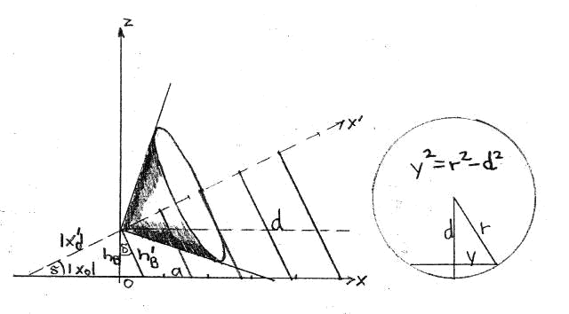
The snow cover halos of the sun are a preliminary stage to understanding the snow cover halos at earthly light sources. As already described in Part 1 of the work, to illustrate halos of the sun, one can use a cone with its tip at the observer's eye. This cone now intersects the flat snow cover, causing the halo to appear on it as a conic section. It should be noted that this involves only a single cone and not a double cone as in classical conic section geometry. The halo curve must be a hyperbola. This is because the formation of parabolas necessarily requires that one of the rays of the ray pair representing the cone in the x,z-plane is parallel to the x-axis. This is only possible if the cone doesn't intersect the snow cover at all (at most touches for $h_B = 0$) or if the sun with the half opening angle alpha of the cone is below the horizon, where naturally no more light falls on the snow cover. For ellipses, it would have to be even lower so that the second ray also intersects the x-axis and a closed curve is formed. Only at an eye height of 0 can the intersection image present itself as a line or pair of lines. However, in the projection, the eye sees the edge of the crystal surface, resulting in only one or two luminous points instead of a ring as a snow cover halo. In fact, the halos must always be circles from the observer's perspective, because the eye receives light from a cone surface. Since the eye is the cone's tip, the halo is always the same size regardless of its distance (same angular distance to the sun), which also helps when the distance within the halo changes, as is the case with the hyperblast.
\begin{equation*}
r = \tan \alpha * x'
\end{equation*} \begin{equation*}
|x_0'| = {h_B \over \sin \delta}
\end{equation*}
r = \tan \alpha * x'
\end{equation*} \begin{equation*}
|x_0'| = {h_B \over \sin \delta}
\end{equation*}
\begin{equation*}
h_B' = {h_B \over \cos \delta}
\end{equation*} \begin{equation*}
|x_0'| = {h_B \over \tan \delta}
\end{equation*}
h_B' = {h_B \over \cos \delta}
\end{equation*} \begin{equation*}
|x_0'| = {h_B \over \tan \delta}
\end{equation*}
\begin{equation*}
d = \tan \delta * x' + h_B'
\end{equation*} \begin{equation*}
\cos \delta = {{x' + {h_B \over \sin \delta}} \over {x + {h_B \over \tan \delta}}}
\end{equation*}
d = \tan \delta * x' + h_B'
\end{equation*} \begin{equation*}
\cos \delta = {{x' + {h_B \over \sin \delta}} \over {x + {h_B \over \tan \delta}}}
\end{equation*}
\begin{equation*}
x' = \cos \delta \left(x + {h_B \over \tan \delta}\right) - {h_B \over \sin \delta}
\end{equation*}
x' = \cos \delta \left(x + {h_B \over \tan \delta}\right) - {h_B \over \sin \delta}
\end{equation*}
\begin{equation*}
y^2 = \tan^2 \alpha * x'^2 - (\tan \delta * x' + h'_B)^2
\end{equation*}
y^2 = \tan^2 \alpha * x'^2 - (\tan \delta * x' + h'_B)^2
\end{equation*}
As can be seen from the drawing, a new axis x' is established. With this, the cone radius r is determined, and at the same time, the distance to the x-axis perpendicular to x' is calculated. Since the new axis setting corresponds to a rotation of the coordinate system where y has been mapped onto itself, y can also be determined directly with the new coordinates. Here, the circularity of the cone cross-section is utilized, and the square of y is determined using the Pythagorean theorem. It should be noted that there are two symmetrical solutions for y, and therefore the halo cut cannot be represented as a function. Furthermore, this results in symmetry to the x-axis and thus in angular coordinates to the height circle of azimuth 0 ("prime meridian").
A relation between x and x' is given as follows:
\begin{equation}
x' = x * \cos \delta - h_B * \sin \delta
\end{equation}
x' = x * \cos \delta - h_B * \sin \delta
\end{equation}
The final equations for the snow cover halos are:
\begin{equation}
y^2 = r^2 - (x * \sin \delta + h_B * \cos \delta)^2
\end{equation} \begin{equation}
y^2 = \tan^2 \alpha (x * \cos \delta - h_B * \sin \delta)^2 - (x * \sin \delta + h_B * \cos \delta)^2
\end{equation}
y^2 = r^2 - (x * \sin \delta + h_B * \cos \delta)^2
\end{equation} \begin{equation}
y^2 = \tan^2 \alpha (x * \cos \delta - h_B * \sin \delta)^2 - (x * \sin \delta + h_B * \cos \delta)^2
\end{equation}
Since the applied method is also suitable for describing intersection curves of other rotational bodies (circular cross-section), the expression for r has not yet been used in (15). This formula will play a role in the calculation of lamp snow halos.
For an x that approaches infinity, a corresponding y arises. However, this is not the case with the quotient y / x. It approaches a certain value, which can be proven by transforming y / x (where all summands drop out if the power of x in the denominator is greater). But since y / x represents the azimuth, which is identical to the central angle at infinite x (phi=0, vanishing point properties), the result of the calculation corresponds to the half-angle that the halo reaches at the horizon (maximum extent). Due to symmetry, it is to be doubled to obtain the actual extent.
\begin{equation}
E_{max} = 2 arc * \tan \sqrt{\tan^2 \alpha * \cos^2 \delta - \sin^2 \delta}
\end{equation}
E_{max} = 2 arc * \tan \sqrt{\tan^2 \alpha * \cos^2 \delta - \sin^2 \delta}
\end{equation}
In addition, the distance of the nearest halo point (zero point of the halo function, under which the unique calculation rule for y² is understood) can be calculated as follows:
\begin{equation}
a = {h_B \over \tan(\alpha - \delta)}
\end{equation}
a = {h_B \over \tan(\alpha - \delta)}
\end{equation}
4. Snow Cover Halos Below Terrestrial Light Sources
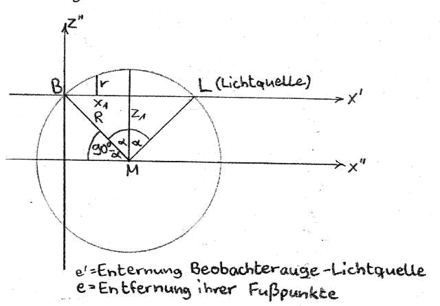
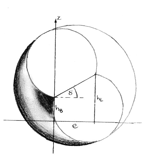
This brings us now to the actual core of the calculations, namely the description of snow cover halos under terrestrial light sources. First of all, it is necessary to establish a function for y². This can be done with (15), however, the altered calculation of the rotation body radius must be considered.
$z''$ - Value of the x-axis:
\begin{equation*}
z_1 = {x_1 \over \tan \alpha}
\end{equation*} \begin{equation*}
R = {x_1 \over \sin \alpha}
\end{equation*} \begin{equation*}
r = \sqrt{{x_1^2 \over \sin^2 \alpha} - \left( x' - x_1 \right)^2} - {x_1 \over \tan \alpha}
\end{equation*}
z_1 = {x_1 \over \tan \alpha}
\end{equation*} \begin{equation*}
R = {x_1 \over \sin \alpha}
\end{equation*} \begin{equation*}
r = \sqrt{{x_1^2 \over \sin^2 \alpha} - \left( x' - x_1 \right)^2} - {x_1 \over \tan \alpha}
\end{equation*}
Circle:
\begin{equation*}
z''^2 = R^2 - (x' - x_1)^2
\end{equation*} \begin{equation*}
z''^2 = {x_1^2 \over \sin \alpha} - (x' - x_1)^2
\end{equation*} \begin{equation*}
x_1 = {e' \over 2} = {e \over 2 \cos \delta}
\end{equation*}
z''^2 = R^2 - (x' - x_1)^2
\end{equation*} \begin{equation*}
z''^2 = {x_1^2 \over \sin \alpha} - (x' - x_1)^2
\end{equation*} \begin{equation*}
x_1 = {e' \over 2} = {e \over 2 \cos \delta}
\end{equation*}
From the illustration, one can determine the radius of the solid of revolution at point x' on the axis of rotation as follows:
\begin{equation}
r = \sqrt{{e^2 \over 4 \cos^2 \delta * \sin^2 \alpha} - \left(x' - {e \over 2 \cos \delta}\right)^2} - {e \over 2 \cos \delta * \tan \alpha}
\end{equation}
r = \sqrt{{e^2 \over 4 \cos^2 \delta * \sin^2 \alpha} - \left(x' - {e \over 2 \cos \delta}\right)^2} - {e \over 2 \cos \delta * \tan \alpha}
\end{equation}
This is used for r while simultaneously performing the transformation to x:
\begin{equation}
y^2 = \left(\sqrt{{e^2 \over 4 \cos^2 \delta * \sin^2 \alpha} - \left(x * \cos \delta - h_B * \sin \delta - {e \over 2 \cos \delta}\right)^2} - {e \over 2 \cos \delta * \tan \alpha}\right)^2 - (x * \sin \delta + h_B \cos \delta)^2
\end{equation}
y^2 = \left(\sqrt{{e^2 \over 4 \cos^2 \delta * \sin^2 \alpha} - \left(x * \cos \delta - h_B * \sin \delta - {e \over 2 \cos \delta}\right)^2} - {e \over 2 \cos \delta * \tan \alpha}\right)^2 - (x * \sin \delta + h_B \cos \delta)^2
\end{equation}
The tangent of the height of the light source is the height difference between lamp height ($h_L$) and eye level ($h_B$) divided by the distance of the base points ($e$).
\begin{equation}
\tan \delta = {h_L - h_B \over e}
\end{equation}
\tan \delta = {h_L - h_B \over e}
\end{equation}
As with the solar halo, the lamp height must be in the range between $\alpha$ and $-\alpha$ (where the minimal deviation is generalized). However, this is only a necessary condition because answering the question of the formation of a snow cover halo precisely requires calculating the zeros of the halo function or calculating the nearest and farthest halo point. This is done by completing the lower circular arc of the body cut in the x,z-plane into a full circle. Then, the position of its center and from that the positions of the intersections with the x-axis can be determined, which are symmetrical to the x-value of the center and represent the zeros of the halo function. From this quadratic equation, the discriminant D is obtained:
\begin{equation}
D = {e^2 \over 4 \cos^2 \delta * \sin^2 \alpha} - {1 \over 4} \left(h_B + h_L + {e \over \tan \alpha} \right)^2
\end{equation}
D = {e^2 \over 4 \cos^2 \delta * \sin^2 \alpha} - {1 \over 4} \left(h_B + h_L + {e \over \tan \alpha} \right)^2
\end{equation}
For a D>0, there are two intersection points, and thus a halo ring; otherwise, no snow cover halo is formed. If eye level and lamp height are each increased by the same amount, the ring converges at the x-coordinate of the midpoint, as D and thus the distance of the zeros become smaller. However, this coordinate is not identical to the x-value where the maximum y² is reached, that is, where the halo curve is widest. For lamp heights different from zero, this does not lie in the middle of the zeros a and b.
\begin{equation}
a;b = {e \over 2} \left(1 - {\tan \delta \over \tan \alpha} \right) \pm \sqrt{{e^2 \over 4 \cos^2 \delta * \sin^2 \alpha} - {1 \over 4} \left(h_B + h_L + {e \over \tan \alpha} \right)^2}
\end{equation}
a;b = {e \over 2} \left(1 - {\tan \delta \over \tan \alpha} \right) \pm \sqrt{{e^2 \over 4 \cos^2 \delta * \sin^2 \alpha} - {1 \over 4} \left(h_B + h_L + {e \over \tan \alpha} \right)^2}
\end{equation}
From the zeros, the vertical diameter gamma of the halo in the projection can be determined quite easily. For this, the heights of the zeros are simply subtracted. Due to the measurement along great circles, the actual angular difference is also determined.
\begin{equation}
y = \arctan \left(h_B \over a \right) - \arctan \left(h_B \over b \right)
\end{equation}
y = \arctan \left(h_B \over a \right) - \arctan \left(h_B \over b \right)
\end{equation}
More difficult is the determination of the horizontal diameter $\varepsilon_{max}$. First, a function must be determined that indicates the extent of the halo in angular measure for each x. For this, the following applies:
\begin{equation}
\varepsilon = 2 \arctan \left( |y| \over \sqrt{h_B^2 + x^2} \right)
\end{equation}
\varepsilon = 2 \arctan \left( |y| \over \sqrt{h_B^2 + x^2} \right)
\end{equation}
It should be noted that the horizontal diameter must be measured along great circles as well. Since the expansion y is divided by the distance to the corresponding x-value at y=0, an angular measurement is practically made along the straight grid line for this x and thus measured along a great circle. The maximum of these horizontal chords can be determined quite precisely by calculating the zero of the derivative of (25), as is done in the program. Since no closed calculation is possible, the computer uses a form of interval nesting that is similar to the Regula falsi. Initially, (25) can be rearranged so that the root goes over the entire argument of the arctangent and the square of y is in the numerator. Subsequently, to simplify the zero calculation of the derivative, one can omit the factor 2, the arctangent, and the root, as these monotonically increasing functions do not change the x-value of the zero. Finally, using (20), the quotient rule is employed. For reasons of clarity, some terms are substituted:
\begin{equation*}
g = {e^2 \over 4 \cos^2 \delta * \sin^2 \alpha}
\end{equation*} \begin{equation*}
h = \cos \delta
\end{equation*} \begin{equation*}
i = h_B * \sin \delta + {e \over 2 \cos \delta}
\end{equation*}
g = {e^2 \over 4 \cos^2 \delta * \sin^2 \alpha}
\end{equation*} \begin{equation*}
h = \cos \delta
\end{equation*} \begin{equation*}
i = h_B * \sin \delta + {e \over 2 \cos \delta}
\end{equation*}
\begin{equation*}
j = {e \over 2 \tan \alpha * \cos \delta}
\end{equation*} \begin{equation*}
k = \sin \delta
\end{equation*} \begin{equation*}
l = h_B * \cos \delta
\end{equation*}
j = {e \over 2 \tan \alpha * \cos \delta}
\end{equation*} \begin{equation*}
k = \sin \delta
\end{equation*} \begin{equation*}
l = h_B * \cos \delta
\end{equation*}
From this, one obtains the halo function and its derivative as follows:
\begin{equation*}
y^2 = \left( \sqrt{g - \left( h * x - i \right)^2} - j \right)^2 - (k * x + l)^2 = h(x)
\end{equation*} \begin{equation}
(y^2)' = -2h \left( 1 - {j \over \sqrt{g - (h*x - i)^2}} \right) * (h * x - i) - 2k (k * x + l) = h'(x)
\end{equation}
y^2 = \left( \sqrt{g - \left( h * x - i \right)^2} - j \right)^2 - (k * x + l)^2 = h(x)
\end{equation*} \begin{equation}
(y^2)' = -2h \left( 1 - {j \over \sqrt{g - (h*x - i)^2}} \right) * (h * x - i) - 2k (k * x + l) = h'(x)
\end{equation}
horizontal chords:
\begin{equation*}
\varepsilon = 2 * \arctan \sqrt{y^2 \over h_B^2 + x^2}
\end{equation*}
\varepsilon = 2 * \arctan \sqrt{y^2 \over h_B^2 + x^2}
\end{equation*}
is reduced to:
\begin{equation}
m = {y^2 \over h_B^2 + x^2} = i(x)
\end{equation> (same zeros of the derivative) \begin{equation>
m' = {h'(x) * \left( x^2 + h_B^2 \right) - h(x) * 2x \over \left( x^2 + h_B^2 \right)^2} = i'(x)
\end{equation> From $i'(x_{max}) = 0$, $x_{max}$ is calculated iteratively, from which $\varepsilon_{max}$ is then determined.
5. The Underlamp (Mirror image of the lamp on horizontal crystal surfaces)
This and the following sections present means for calculating other theoretically possible halo phenomena in ice fog and on a snow cover. The first of these phenomena is the one that corresponds to the subsun (analogous to a sublamp). We have not yet been able to observe it. However, Minnaert describes it in his book (Chapter 26) in connection with light tracks on the snow. These light tracks, due to their similarity to light pillars, also represent halo phenomena on the snow cover! They arise from crystal surfaces that are not exactly horizontally oriented. As long as there are no lateral rotations of the surfaces, the tracks always lie on the x-axis, as does the sublamp. Its calculation is based on an auxiliary figure (ellipse). The ellipse is defined in a section in the x,z-plane such that the observer's eye and the light source are its foci and it touches the x-axis. This is done because, with ellipses, the connecting lines from the foci to a tangent's point of contact form the same angle with it. The requirement for equality of the two angles results from the law of reflection. In the case of the subsun, however, it is quite simple, since from the parallel beam course it immediately follows that it stands with the height of the sun below the horizon.
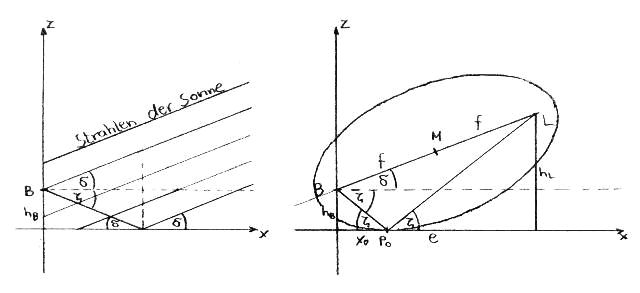
Important parameters of the ellipse are the following:
Midpoint: $M \left( {e \over 2} | {h_B + h_L \over 2} \right)$
Tangent: x-axis
Point of tangency: $P_0(x_0|0)$
Slope of the main axis: $\tan \delta = {h_L - h_B \over e}$
Linear eccentricity: $f = {e \over 2 \cos \delta}$
This information is not sufficient to uniquely construct the ellipse or calculate it, as at least one of the axes or semi-axes must be known. A statement from "Algebra and Geometry" helps here, which states that the product of the distances of the foci on the tangent (i.e., eye level and lamp height) is equal to the square of the minor semi-axis.
The following illustration shows the ellipse in a rotated coordinate system. In it, it can be described with the general ellipse equation (symmetry axes parallel to coordinate axes). For this, the center coordinates are calculated using the equations for coordinate transformation and the minor semi-axis is determined from eye and observer height. Finally, the major semi-axis is obtained from linear eccentricity and minor semi-axis with the Pythagorean theorem. From the ellipse equation in rotated coordinates, the one in the original coordinates is determined. From this, the zero point is calculated (only one solution due to uniqueness). The very extensive expression can be extremely simplified.
Ultimately, one obtains the x-value of the lower lamp and its height below the horizon:
\begin{equation}
x_0 = {e \over 2} \left( 1 - {h_L - h_B \over h_L + h_B} \right)
\end{equation} \begin{equation>
\tan \zeta = - \tan \delta - {2h_B \over e}
\end{equation}
x_0 = {e \over 2} \left( 1 - {h_L - h_B \over h_L + h_B} \right)
\end{equation} \begin{equation>
\tan \zeta = - \tan \delta - {2h_B \over e}
\end{equation}
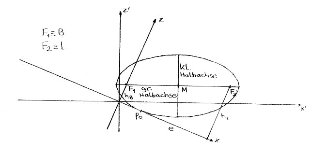
Equation (30) also states that for a large distance from the light source, the height of the underlamp more and more approaches the negative value of the light source height, until both coincide at infinite distance (like sub-sun).
6. The Side Lamps
According to current knowledge, side lamps can only occur in ice fog, as they lie on the azimuthal circle of the lamp (same height) and never reach the snow cover. Additionally, the crystals in the ice fog must be plate-shaped and float stably in a horizontal position with the flat surfaces. They are likely described by two arcs, which are part of a spindle body with a deflection angle greater than or equal to that of the corresponding halo (calculable deviation of the parhelia). They span the actual spindle body like barrel bands and lie on the cone representing the lamp's azimuthal circle in space (small circle, horizon exception). From the observer's perspective, two stripes running towards the light source are visible, with the brightness maximum reached at the beginning of the stripe. There may be even better descriptive models.
7. The Opposite Lamps and the Horizontal Circle of a Lamp
Both phenomena require ice crystals with vertical surfaces. The area of the horizontal circle in space is very complicated to describe, especially since it does not represent a figure rotating around the z-axis, like the horizontal circle of the sun (cone with the apex at the observer's eye, small circle in space). A horizontal circle at a lamp was already described by Minnaert (Chapter 175) in connection with a light pillar.
The counter lamps, on the other hand, can be relatively easily represented by a section in the x,z-plane, since the spatial manifestation of the phenomenon, the observer, and the lamp lie in this plane. Basically, one can approach the problem similarly to the under lamp, but the tangent is no longer the x-axis but a parallel to the z-axis in space. Its distance is arbitrary, as the entire space is filled with crystals. On the other hand, the center and focal points of the ellipse remain.
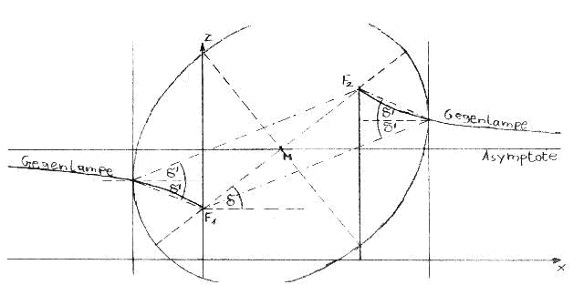
For calculation, the distance of the tangent (x-value of the reflecting crystal) is gradually changed, and the z-value of the crystal is determined by finding the ellipse point with a perpendicular tangent. The result is surprising. Reflections occur not only in the area of the negative x-axis but also behind the lamp (hence the plural form of the term counter-lamp). The curves in space, which indicate the positions of the reflecting crystals, are hyperbola segments (in the sense of inverse proportionalities). Their horizontal asymptote is the line through the midpoint of the segment from the observer to the lamp parallel to the x-axis. By differentiation, it can be proven that the counter-lamp stands behind the observer in its immediate vicinity at an angle delta above the horizon. This explains why the counter-sun is a straight line in space. Similar to the ring halos, only the immediately next segment plays a role here. Because no ice crystals occur behind the sun, the second counter-lamp is omitted. The calculation for both applies:
\begin{equation}
z = {h_L - h_B \over 2} \left( 1 - {e \over e - 2x} \right) + h_B
\end{equation} $x < 0; x > e$
z = {h_L - h_B \over 2} \left( 1 - {e \over e - 2x} \right) + h_B
\end{equation} $x < 0; x > e$
It is important to consider the strict mathematical sign regulation, i.e. the x-values of one lamp are all negative, those of the other always positive and greater than e.
Special cases occurring with certain parameters are explained in more detail in the horizontal circle.
When calculating the horizontal circle, it is not enough to consider only ellipses. Rather, one must use rotational ellipsoids ("...eggs") for calculation. Of these bodies, only the focal points and the center are known. To solve the problem, a parameter $x_1$ is used, which determines the ellipsoid shape. From the now known ellipsoid equation, a section curve is calculated, which is formed by all points of the ellipsoid with vertical tangents. The points of the section curve are then certainly on the horizontal circle. By changing the parameter, all points can be gradually captured.
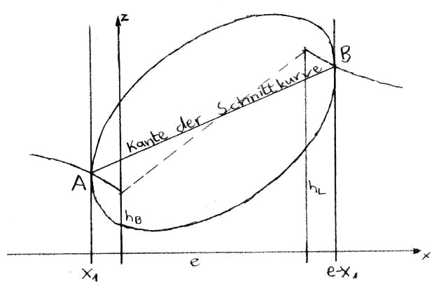
If you connect the points of contact of vertical tangents in the x,z-plane with a straight line, you get the depiction of the desired intersection curve in this plane, i.e., seen from far away standing on the y-axis, you see the edge of this curve, which lies obliquely in a plane in space. The parameter used is the (negative) x-coordinate of the outermost point of contact, i.e., the indication of how far the ellipsoid extends into the negative range. The z-coordinate of the point can be calculated using the counter lamp formula. Finally, you get the following line equation for the edge of the intersection curve:
\begin{equation}
z = {(h_L - h_B) e \over (e - 2x_1)^2} * (x - x_1) - {(h_L - h_B) e \over 2e - 4x_1} + {h_B + h_L \over 2}
\end{equation}
z = {(h_L - h_B) e \over (e - 2x_1)^2} * (x - x_1) - {(h_L - h_B) e \over 2e - 4x_1} + {h_B + h_L \over 2}
\end{equation}
If the parameter $x_1$ < 0 and the x-value of any horizontal circle point are known, z can thus be calculated. By calculating the ellipsoid axes from the parameter using a similar method to that used for the under lamp (product of the tangent distances of the focal points = small semi-axis squared) and considering the circular ellipsoid cross-section, a calculation possibility for y is obtained:
\begin{equation}
x'm = {e \over 2} \cos \delta + {h_B + h_L \over 2} \sin \delta
\end{equation} \begin{equation}
z'm = {h_B + h_L \over 2} \cos \delta - {e \over 2} \sin \delta
\end{equation} \begin{equation}
{(x \cos \delta + z \sin \delta - x'm)^2 \over x_1^2 - ex_1 + {e^2 \over 4 \cos^2 \delta}} + {(z \cos \delta - x \sin \delta - z'm)^2 + y^2 \over x_1^2 - ex_1} = 1
\end{equation}
(z is determined with (32))
The choice of a parameter in regular steps has the disadvantage that no uniform distribution of points in space is achieved. This is disadvantageous when a horizontal circle is to be represented from the observer’s perspective in order to obtain information about light concentrations or similar. Therefore, x and y are replaced as follows:
\begin{equation}
x = \cos \varphi * l
\end{equation} \begin{equation}
y = \sin \varphi * l
\end{equation}
x = \cos \varphi * l
\end{equation} \begin{equation}
y = \sin \varphi * l
\end{equation}
l indicates the distance to a point in space measured in the x,y plane. phi represents the already explained azimuth. Now from (35.) $x_1$ can be iteratively calculated, allowing for a determination of the third coordinate z with (32).
The horizontal circle approaches the plane through the midpoint of the observer-lamp line asymptotically from all sides, parallel to the x,y plane from above or below. Certain points (on the line parallel to the x,y plane and the y,z plane through the mentioned midpoint) or the special cases (see below) already lie on this plane.
In the immediate vicinity of the observer, the horizontal circle corresponds to a cone with the axis of rotation z (e.g., sun). On a larger scale, the horizontal circle has only two symmetric halves (symmetry plane x,z) and resembles a bent cone with a tip (lamp). From the observer's perspective, the greatest light concentration is visible on the horizon (large distances of the crystals), and a lesser one on the azimuthal circle of the lamp near it. However, different results are obtained when considering the crystal's distance. For this, the length of the light path is calculated as the sum of distances from the observer and the lamp to the crystal. The unit used is the distance between the observer and the lamp (to be calculated from e and delta) as the direct light path. Since the light weakens with the square of the distance, the reciprocal and the square of the obtained result are formed. The resulting number is less than 1 and can be understood as the reflection probability. By comparing it with a random number, a simulation program would decide whether the crystal is represented as a point or omitted.
Finally, some special cases should be mentioned:
Same height of observer and light source: The horizontal circle is flat and corresponds to the horizon.
Lamp directly above/below observer: The crystals also lie in a plane through the mentioned midpoint. A uniform light concentration towards the horizon can be seen.
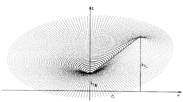
Top view of a horizontal circular area in space with the parameters: $h_B = 1.5m; h_L = 5m; e = 4.5m$
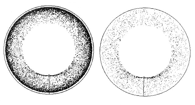
Simulation in equidistant projection generated by random choice of phi and l in the range from $0.15m < l < 30m$ at 15000 rays without and with consideration of the quadratic intensity decrease with distance.
8. Explanation Model for Rainbows from Earthly Light Sources
Rainbows can also be caused by earthly light sources (e.g., with a garden hose or as a fog bow). Since the angles of deflection relative to the light source are 138° (primary bow) and 129° (secondary bow), the corresponding models resemble ring bulges or apples. Their intersection with the ground as a fog bow can take on even more varied shapes than with snow cover halos. They can also be calculated similarly if the changed and partially ambiguous determination of the rotation body's radius is considered. This example, in particular, illustrates the importance of light concentrations, as a fog bow remains a ring, which is due to the fact that many droplets are visible one after the other at the conical end (slight deviations from the inscribed cone). The actual bulge in space is not visible.
Rotational body in "apple shape" (ring bulge partially cut open for display)
by Alexander Haußmann